FPGAs & Arduino Drive Motor Control

Any engineer who’s ever designed an electromechanical system that pushed, pulled, turned, or spun is intimately familiar with motor control. Its application is so widespread that even simple microcontrollers (MCUs) provide the clock speed and signal processing performance to drive complex motors with variable speeds and loads.
But how much is too much for these resourceful little MCUs? What if you’re using a high-resolution quadrature encoder to measure motor speed or direction? What if you need to drive more than one or two motors at a time?
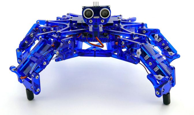
Meet Hexy the Hexapod (Figure 1). Hexy is a low-cost, Arduino-based robotics kit from ArcBotics. The robot contains three servo motors on each of its six legs, plus one on its head, for a total of 19 servo motors.
Since Hexy was designed for the Arduino community, it is compatible with a number of 8- to 32-bit MCUs. These MCUs perform admirably in simple tasks like sequentially driving the motors on each of Hexy’s legs. But when an interrupt service routine is introduced—as it would in any system using a quadrature encoder—the MCUs start to struggle.
One solution for these more complex use cases is an FPGA accelerator.
Avoid the Pains of Programming
A primary advantage of FPGAs is that they can be reprogrammed, allowing them to meet the exact requirements of an application. FPGA fabric can be optimized to the precise determinism, control, and jitter requirements of PWM signals that drive a motor. More FPGA logic blocks can be configured to support additional motors, providing a level of parallelism that isn’t available from other embedded processor architectures.
In fact, the ability to configure FPGAs to exact system requirements can make them more suitable than robust, high-end motor control MCUs, DSPs, and ASICs for motor control applications.
The video in Video 1 shows a motor control demo controlled by 8- and 32-bit MCUs on the Hexy robot. As you can see, the robot’s arms begin to twitch when 50 µs interrupts are introduced; there are simply too many concurrent tasks for the MCUs to compensate for jitter in the PWM signal that drives the servos.
Video 1. A motor control demonstration with 8- and 32-bit MCUs struggling to execute concurrent tasks on the Hexy robot. (Source: Alorium Technology)
The video goes on to show how effective the parallelism and precision of an FPGA can be in complex, interrupt-based, multi-motor drive use cases. Rather than using multiple processors or control boards, a single FPGA can drive a number of motors and read and process quadrature data. This reduces design cost, power consumption, and system size.
But FPGA programming has historically made engineers run for the hills. That’s because VHDL and Verilog—the two primary hardware description languages (HDL) used to describe the structure of FPGA fabric—are actually electronic design automation (EDA) paradigms.
These languages do not operate like typical software. Complex logic synthesis tools are needed to convert HDL code into a design implementation that defines logic gates, generates bitstreams, and so on.
For most engineering teams, the decision to use FPGAs comes after weighing the parallelism and performance gains against the pains of programming. One company designing custom BLDC motor control applications for unmanned aerial vehicles (UAVs) recently found itself at these crossroads.
To avoid making a tradeoff, it partnered with Alorium Technology, a developer of FPGA-accelerated embedded solutions.
Enhanced Custom BLDC Motor Control
The UAV company began designing the BLDC system around MCUs, and was using the Arduino IDE to write and test its motor control software. The application required a processing element that could run the motors at extremely high, variable speeds, and also read sensor data. Eventually, the system became too complex to run on an MCU, and the decision was made to migrate to custom hardware.
The main problem with this decision was that the company’s entire codebase had been designed in and around the Arduino environment. This meant whatever compute architecture chosen for its motor control system had to efficiently run Arduino’s simplified C++ code.
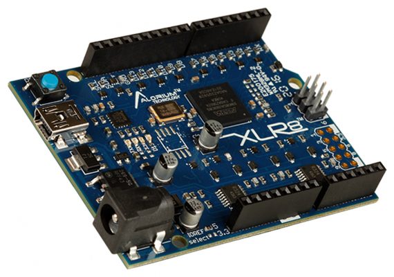
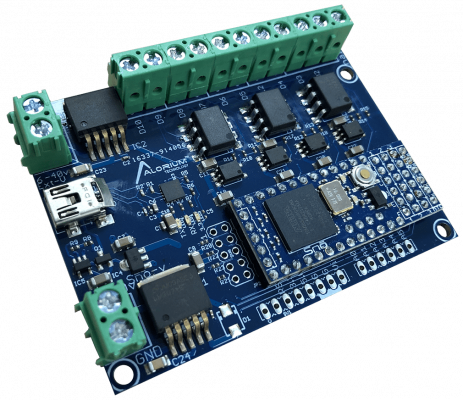
The company arrived at Alorium Technology’s XLR8 development board (Figure 2). XLR8 is an Arduino-programmable, FPGA-based prototyping platform with an embedded 8-bit AVR MCU. The board is a form factor- and pin-compatible replacement for the Arduino Uno. And the UAV engineering firm was able to drop the board into its design and immediately start running existing code.
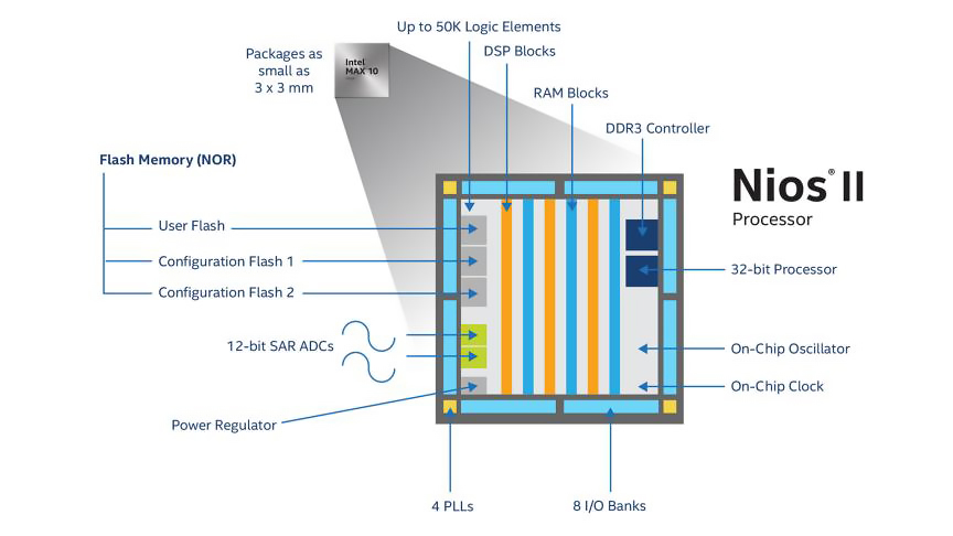
The XLR8 FPGA fabric is based on an Intel® MAX® 10 FPGA with 8,000 logic elements (LEs) and 500 logic array blocks (LABs). With a maximum operating frequency of 450 MHz, it provides more than enough horsepower for even the most sophisticated motor control applications.
The MAX 10 also natively integrates flash memory, ADCs, digital and analog I/O, and other components that make it a cost-effective solution for deployment in industrial use cases (Figure 3).
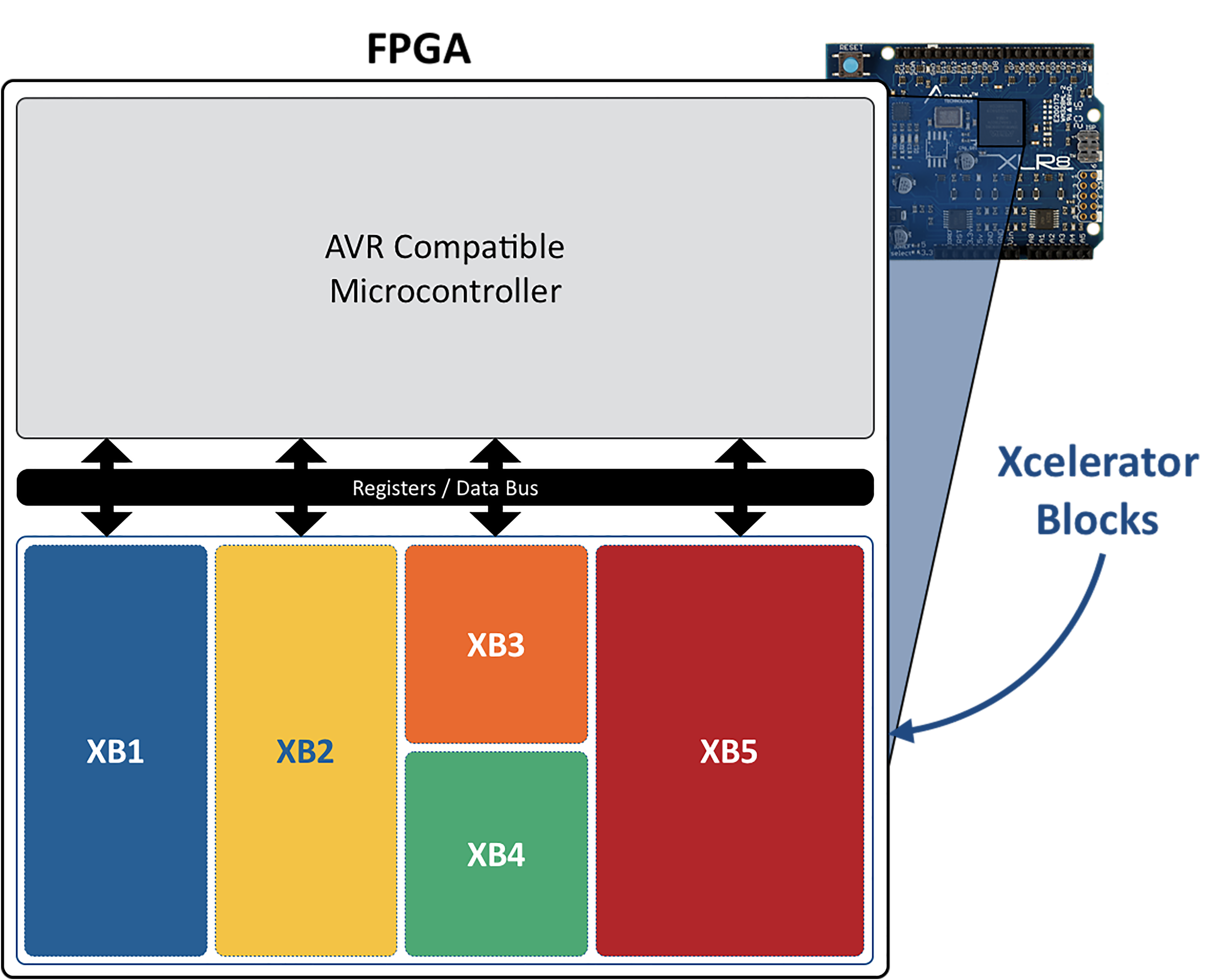
But what made the XLR8 development board so attractive to the custom UAV BLDC design was the presence of function-specific “Xcelerator Blocks,” or XBs. XBs are integrated into the MAX 10 FPGA fabric to optimize the performance of certain functions, such as servo control, quadrature encoding, analog to digital conversion, floating-point math, and so on.
XBs communicate with the AVR MCU via an addressable register interface (Figure 4). And thanks to XB libraries from Alorium that can be installed in the Arduino IDE, users can access their functionality using standard API calls. No code modifications are required. It is even possible to update the FPGA image through the Arduino IDE.
To support unique control algorithms used in the BLDC application, custom hardware was required. Alorium customers are able to create their own specialized XBs using a methodology called OpenXLR8. This does require VHDL or Verilog coding but provides a templated environment for users. It even generates Arduino-compatible .RPD files.
In the case of the UAV project, Alorium assisted with the development of several custom hardware blocks. These included:
- RC Input XB that interprets incoming signals from a radio control device
- PWM XB that implements a configurable PWM along with a three-phase sinusoidal PWM
- Hall Sensor XB that provides static tuning of signals before sending them to the motor control XB
- The ability to dynamically adjust the system based on motor speed
- Proprietary Blocks
Because added BLDC functionality required more FPGA fabric, the UAV design eventually migrated to Alorium’s higher-performance Snō FPGA Module. Snō is production-grade, supporting an 8-bit MCU and Arduino compatibility. And it also upgrades the FPGA to a MAX® 10 with 16k LEs.
As the UAV system neared production, it needed protection against signal noise caused by high-voltage switching. To solve this problem, Alorium developed a noise-immune carrier board for the Snō module called the AT10 (Figure 5).
From Maker to Master
The UAV BLDC case study provides an excellent example of how open-source, educational hardware has taken hold in the professional engineering community.
Beyond this application, Alorium has customers in industries like test, measurement, and scientific instrumentation that require extremely high fidelity from data acquisition and signal processing systems. To scale while meeting many specific use case requirements, its hardware platforms must be flexible. And since the primary users of these systems are scientists or domain experts, novices must become technically proficient with the platform software quickly.
With high-performance, low-cost, Arduino-compatible FPGA solutions, the industry is democratizing programmable logic technology. In some cases, the availability of these solutions will lead to rapid innovation. In many others, it will yield a more efficient, affordable, and scalable way of addressing challenges that already exist.
To download XLR8 images, XBs, and application notes, visit Alorium Technology’s Github.